


Digitizing Plant Engineering End-to-End –
From Design to Commissioning
Industrial plants are large-scale projects with long timelines, many stakeholders, and extensive documentation requirements. We establish seamless data flows, automated engineering, and 3D planning – across all project phases.
©Herbold Meckesheim GmbH
Why Plant Engineering Projects Are So Complex
Long project durations, numerous interconnected systems, and high demands on documentation and traceability make plant engineering particularly challenging.
Every Plant Is a Major Project
Industrial plants consist of hundreds of configurable components – machinery, conveyor technology, utility systems, and controls. Project planning requires months of engineering work, during which dozens of variants must be evaluated, layout plans created, and interfaces coordinated. Every manual iteration costs time and carries the risk of errors.
Lack of Continuous Data Flows
Sales, project planning, engineering, procurement, and assembly teams work with different systems. Configuration data is manually transferred into CAD, bills of materials are separately created in the ERP system, and layout plans are drawn independently. Every interface is a potential source of errors that only becomes apparent on the construction site.

©Herbold Meckesheim GmbH
©Herbold Meckesheim GmbH
Layout Planning in Complex Existing Environments
Industrial plants are frequently integrated into existing production halls. Column grids, utility runs, existing machinery, and accessibility requirements must be taken into account with precision. Manual 2D planning cannot adequately represent this spatial complexity – collisions and planning errors are often only discovered during installation.
Enormous Documentation Effort
Plant projects require extensive technical documentation: layout drawings, interface drawings, bills of materials, utility supply plans, CE documentation, and operating manuals. Manually creating and maintaining these documents over the entire project lifecycle ties up significant engineering capacity.
Use Cases: How Plant Builders Benefit in Practice
Three typical scenarios showing how our solutions transform the engineering, planning, and documentation of industrial plants.

Modular Plant Configuration with 3D Layout Planning
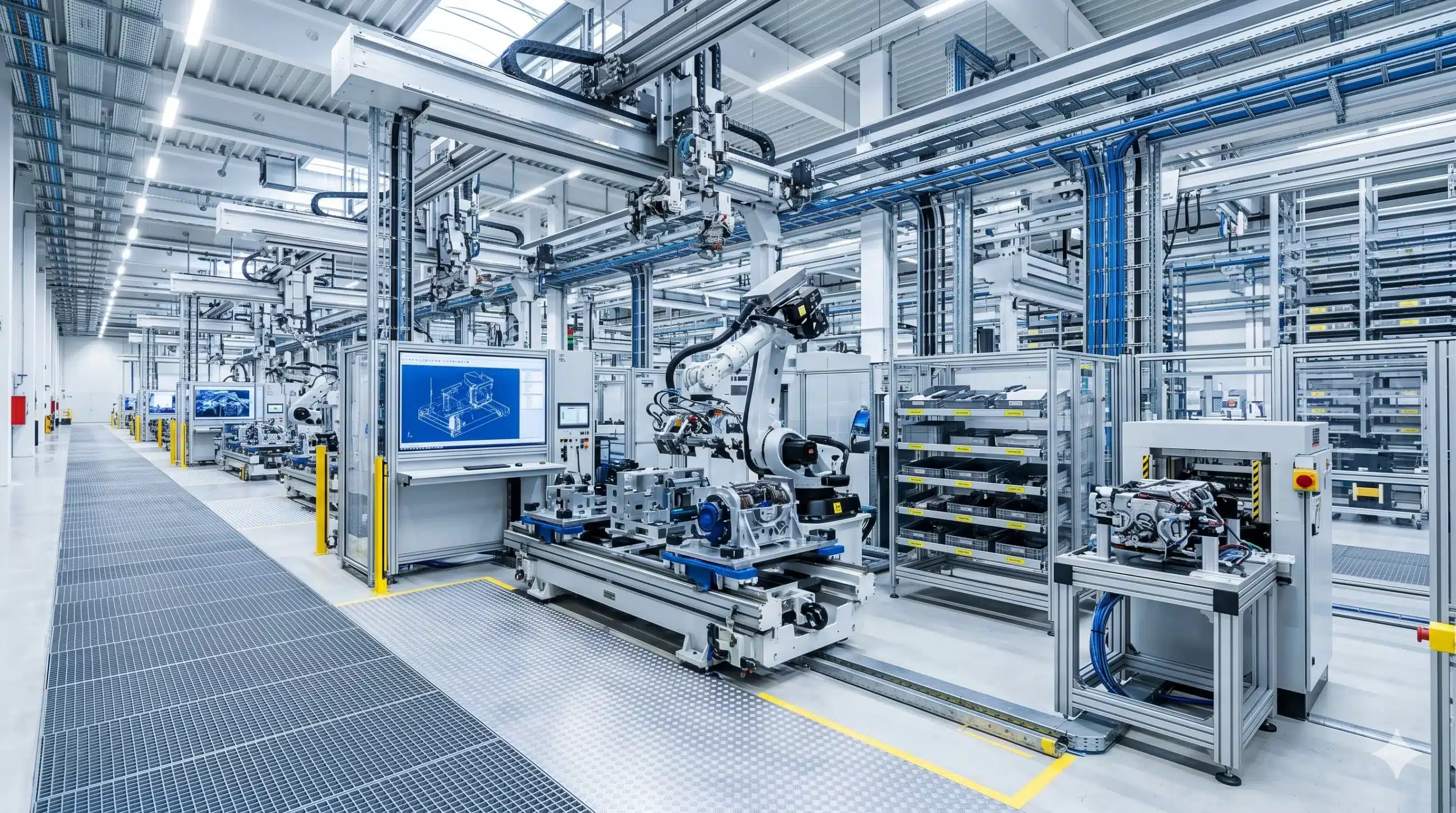
A plant builder uses the CPQ system to configure the individual machine modules of a production plant based on performance, throughput, and process requirements. The system automatically checks the compatibility of modules with one another. In 3D layout planning, the configured modules are placed within the customer’s facility – including conveyor lines, utility connections, and maintenance access points. The customer receives an interactive 3D layout for approval before detailed engineering even begins.
Automated Engineering and Bill of Materials Handover
From the configuration output, the Design Automation software generates 3D models of all project-specific assemblies. Manufacturing drawings with standard-compliant dimensioning are then derived from these models, and bills of materials are transferred directly to the ERP system via system integration – validated, formatted, and revision-safe. The entire process from configuration to production order runs without any manual intervention.

Complete Project Documentation at the Push of a Button
At the end of the project, the complete documentation package is generated automatically: CE declaration of conformity, risk assessment, technical data sheets, operating manuals, and layout plans. All documents are versioned in the PDM/PLM system through system integration and linked to the project in the ERP system. The operator receives a complete, audit-ready handover package – without weeks of manual compilation..
Fully Digitally Planned: Measurable Results.
60 %
faster quote creation for configured plants
3D
layout plans available already in the quotation phase
≥ 35 %
less rework through early collision detection
Software for Plant Engineering
The right software products for modular plant configuration, 3D layout planning, and continuous project data flows.
Tacton CPQ
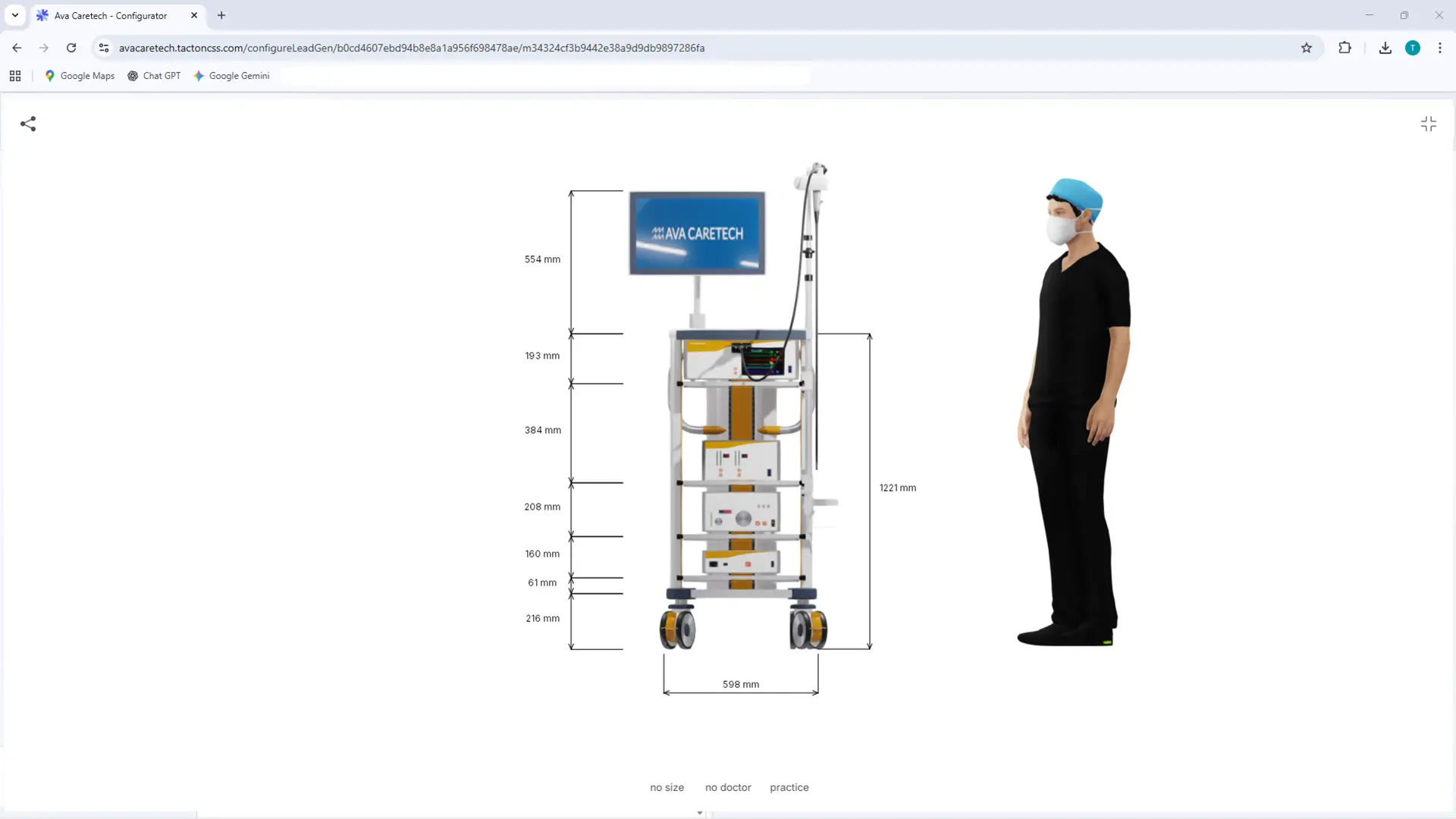
The constraint-based engine intuitively guides users to a technically sound solution. It significantly speeds up the quote generation process and ensures maximum price transparency through automated real-time calculations for the sales team.
Tacton Design Automation
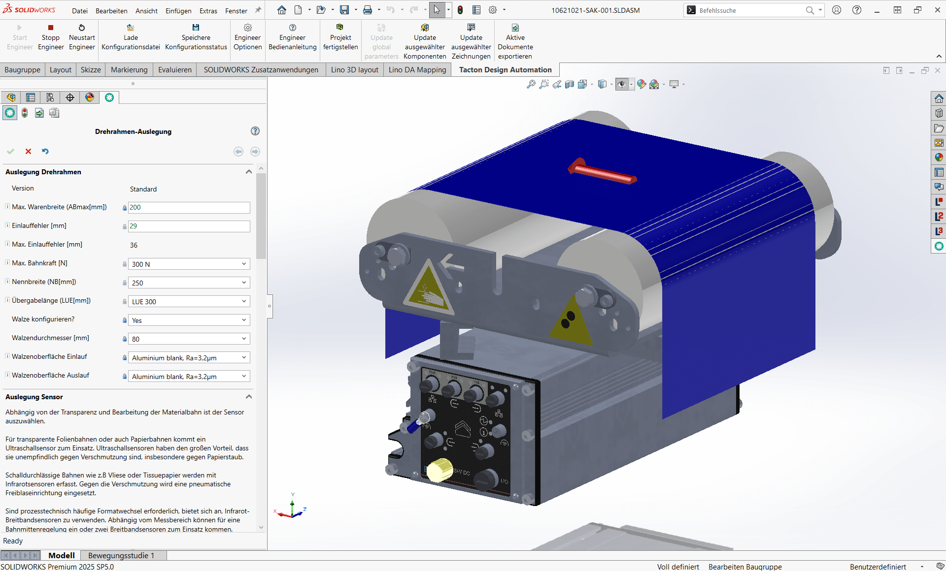
Transforms expert knowledge into intelligent rules to automatically generate complex 3D models, drawings, and bill of materials—saving up to 90% of engineering time.
Lino® Hub
Seamlessly connects sales, engineering, and manufacturing for end-to-end digital processes.
Seamlessly integrates CPQ, CAD, ERP, and PDM for error-free, automated data flows without media breaks.
Lino® 3D layout
Uses drag-and-drop and snap technology for collision-free layouts. Ensures seamless data flow from sales to installation without any data loss.

Relevant Processes
The digital engineering processes supported by Lino connect system integration, configuration, and automation into a seamless value chain – from the first customer contact through to the finished machine system.
Design Automation for Rapid Product Development
Optimize your design process with Design Automation and CAD automation. Product rules automatically generate 3D CAD models, 2D drawings, and bills of materials. This accelerates engineering processes, reduces errors, and significantly decreases routine engineering tasks.
Product Configuration for Individual Customer Solutions
Master product variety with a product configurator and CPQ system. Using rule-based variant configuration and guided selling, sales teams, partners, and customers create technically valid product variants, quotes, and configuration data – directly integrated into CAD and ERP systems.
System Integration for a Seamless Corporate IT Landscape
Connect your IT systems into a continuous data chain. Through system integration in mechanical engineering, CAD, ERP, CRM, and PDM/PLM systems are seamlessly linked. This creates a consistent digital thread along the entire product lifecycle.
Process Automation for Seamless Digital Workflows in Mechanical Engineering
Workflow and process automation connects engineering systems into seamless digital workflows. Automated workflows handle recurring tasks, reduce manual steps, and ensure consistent data between CAD, PDM, ERP, and CRM.
Visualizing 3D Products in the Web Browser
With 3D product visualization on the web, you can present complex products interactively in the browser. Thanks to modern technologies such as WebGL 3D viewers, variants can be displayed in real time and directly linked to configurators or web shops.
Simplified 3D CAD Models for Fast, Reliable Processes
Reduce complex assemblies with CAD model simplification and data reduction. Lightweight models improve the performance of CAD systems and enable the use of models for simulation, VR/AR, or web visualization.
3D Layout Planning for Modern, Impressive Plant Layouts
Plan entire plants with 3D layout planning and digital factory planning. With CAD-based 3D plant planning, you can create layouts, detect collisions early, and validate projects faster.
Together, we analyze your existing workflows and identify concrete potential for more efficient, digital processes – practical, structured, and with a clear focus on measurable value.
- Analysis of your engineering and sales processes
- Identification of optimization potential
- Clear roadmap for your digital transformation
See for Yourself

Frequently Asked Questions
Knowledge base on engineering automation in plant engineering.
Here you will find answers on the end-to-end digitalization of plant projects – from modular configuration through 3D layout planning and automated design to complete project documentation.
Learn how Lino uses CPQ, design automation, system integration, and process automation to shorten long project lead times, detect clashes early, close data flows between sales, engineering, purchasing, and assembly, and deliver a complete, audit-ready handover package at the push of a button.
How does system integration resolve the missing data flows between sales, design, and assembly?
In plant engineering, sales, project planning, design, purchasing, and assembly typically work with different systems – every manual interface is a potential source of errors that often only surfaces on the construction site. End-to-end system integration connects CPQ, CAD, PDM/PLM, ERP, and CRM through standardized interfaces and data models. Configuration data, bills of materials, and layout plans are synchronized automatically between the systems, so that all teams work on a consistent data foundation. This creates an end-to-end digital thread from initial customer contact to commissioning – with no media breaks and no duplicate data maintenance.
How can the documentation effort in plant projects be reduced?
Plant projects require extensive technical documentation: layout plans, interface drawings, bills of materials, utility supply plans, CE declarations of conformity, risk assessments, and operating manuals. Through process automation and drawing automation, these documents are generated rule-based from validated project data, versioned in the PDM/PLM system, and linked to the project in the ERP. Instead of weeks of manual compilation, a complete, audit-ready handover package is created at the push of a button – revision-secure and consistently traceable for the later operation of the plant.
How can design and bill-of-materials handover to the ERP system be automated?
Based on the configuration result, design automation generates the 3D models of all project-specific assemblies rule-based, along with the corresponding manufacturing drawings with standard-compliant dimensioning. Through system integration, bills of materials, item master data, and routings are validated, formatted, and transferred to the ERP system in a revision-secure way – with no manual duplicate entry. The entire path from configuration to production order runs without manual intervention, reducing errors in order processing by at least 30 percent and freeing engineering capacity for complex project tasks.
What role does 3D layout planning play in the quotation phase?
In the quotation phase, spatial feasibility and integration capability often decide whether an order is won. With 3D layout planning, configured machine modules, conveyor lines, utility supply, and maintenance access are placed directly in the customer’s hall within the CAD system – including column grids, media routing, and existing equipment. Early clash detection prevents costly rework on site and typically reduces planning errors by at least 35 percent. The customer receives an interactive 3D layout for approval before detailed design even begins – building trust and accelerating decisions.
How does modular plant configuration with CPQ help in complex large-scale projects?
Industrial plants consist of hundreds of configurable components – machines, conveyor systems, utilities, and control systems. With constraint-based product configuration in a CPQ system, individual modules are combined according to capacity, throughput, and process requirements, while the rule base automatically checks technical compatibility. Sales and project engineering thus generate technically valid plant variants and reliable quotes in a fraction of the previous time – typically around 60 percent faster quotation. Custom and engineer-to-order portions can be integrated seamlessly via a CTO(+) approach.
What does end-to-end digitalization mean in plant engineering?
End-to-end digitalization in plant engineering refers to the seamless connection of all project phases – from sizing through project planning, design, and manufacturing to commissioning – on a unified data foundation. Configuration, CAD, bill-of-materials, and documentation data flow automatically between CPQ, CAD, PDM/PLM, and ERP, without manual transfers or media breaks. Plant builders benefit from shorter quotation cycles, early 3D clash detection, and a consistent digital thread across project lifecycles that often span several years.
Digitizing plant engineering end-to-end means connecting all project phases – from design to commissioning – in one consistent digital process with Lino.