


Conveyor Systems and Hoists: Managing Variants, Accelerating Quotations
Conveyor systems, lifting equipment, and cranes consist of modular assemblies with an enormous variety of options – spans, load capacities, lifting heights, and hall geometries make each system unique. Lino makes this complexity manageable.
© motion06 GmbH
Why Conveyor and Crane Projects Are Particularly Demanding
Individual hall dimensions, stringent standards compliance, and complex installation planning make every project an engineering-intensive undertaking – with extended quotation cycles as a direct consequence:
Individual Sizing for Every Installation Site
Rated loads, spans, lifting heights, and building geometries differ from project to project. Every customer enquiry requires individual technical sizing and engineering – tying up qualified engineers on routine tasks and significantly extending the quotation phase. For a crane manufacturer handling 500+ enquiries per year, this translates into thousands of hours of pure sizing work.
Complex Installation Planning in Existing Facilities
Conveyor systems and cranes must be precisely fitted into existing building structures. Column spacings, roof trusses, utility runs, and installed equipment define the available envelope. Manual 2D layout planning cannot reliably detect collisions – costly surprises during installation and expensive redesigns are the inevitable result.

© motion06 GmbH

© motion06 GmbH
Standards and Safety Regulations
FEM classifications, the Machinery Directive, EN 15011 (overhead travelling cranes), EN 14492 (winches and hoists), and application-specific safety requirements must be observed in every configuration. Manual verification increases the risk of overlooking normative requirements – with potentially serious liability consequences in the event of an operational incident.
Extended Quotation Cycles Due to Technical Clarification
Before a reliable quotation for a conveyor system or crane installation can be issued, it typically passes through three to five iterations between sales, project engineering, and design. Each iteration requires building dimensions, load assumptions, and standards verification. This process commonly takes weeks and delays purchasing decisions – in a market where delivery lead times are a decisive competitive factor.
Use Cases: How Conveyor and Hoist Manufacturers Benefit in Practice
Concrete scenarios showing how our solutions transform configuration, installation planning, and quotation preparation in conveyor technology:
Overhead Travelling Cranes with Individual Spans and Rated Loads
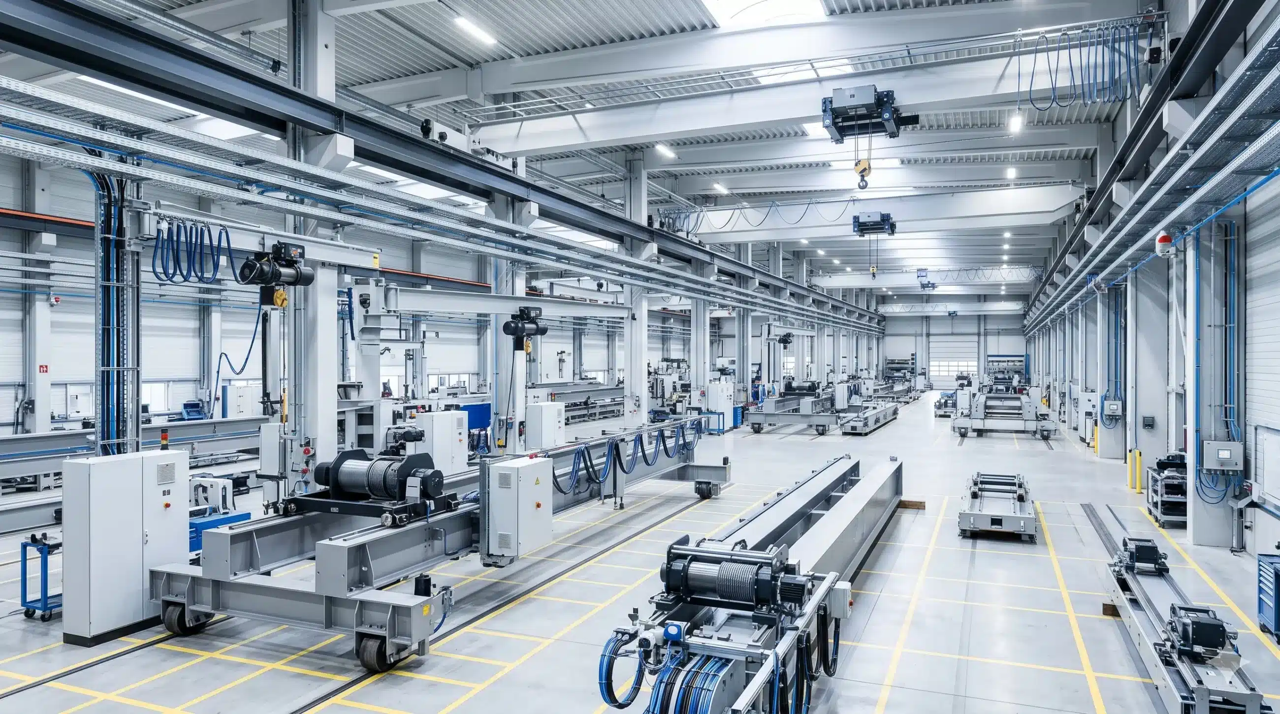
A crane manufacturer uses its CPQ system to configure the precise combination of span, rated load, lifting height, and travel unit type. The system automatically verifies the FEM classification, calculates the required girder cross-section, and dimensions the hoist unit and drives in accordance with applicable standards. Design Automation then generates the complete 3D model, including girder profiles, crab unit, hoist mechanism, and control system mounting. Using 3D installation planning, the crane is fitted into the customer’s facility – with automatic collision checking against roof trusses and building columns. The customer receives a fully substantiated quotation with 3D product visualization within days rather than weeks.

Digital Installation Planning for Belt Conveyor Systems
A conveyor technology supplier imports the floor plan with column grid and elevation data into the CAD system with 3D installation planning. Using drag-and-drop, the sales engineer positions conveyor belt modules, curved sections, transfer stations, and buffer zones. The system automatically detects collisions with building columns, utility runs, and existing machinery, and calculates conveyor lengths and incline angles. The customer receives an interactive 3D visualization of their complete conveyor installation – as a basis for approval and investment decisions, well before detailed engineering commences.

Automated Quotation Drawings for Hoists
For wire rope hoists and chain hoists with variable rated loads, chain reeving arrangements, and suspension options, standards-compliant quotation drawings are generated directly from the configuration output – including suspension details, connection points, and safety markings. Drawing automation ensures that views, sections, and dimensioning are placed in full compliance with applicable standards. The sales team dispatches the complete quotation package with technical drawing within hours – without a single query to the engineering department.
End-to-End Automated: Measurable Results.
60 %
faster quotation preparation
80 %
less manual layout work
100 %
standards-compliant configurations
Software for Conveyor System and Hoist Manufacturers
Our software and solutions address industrial processes precisely where they reach their limits: in managing variant diversity, eliminating manual handoffs, and closing the gaps between sales, engineering, and IT.
Tacton CPQ
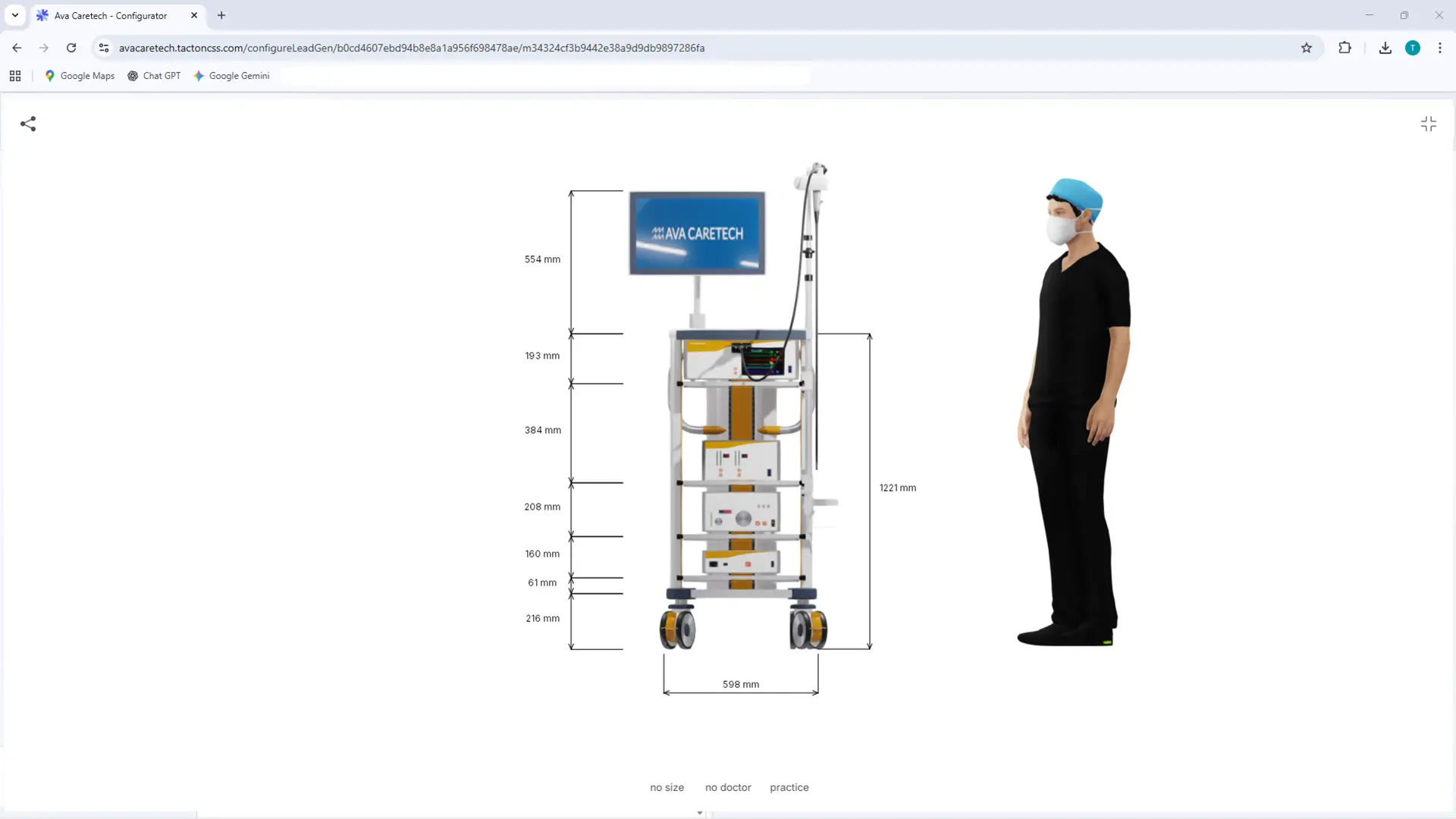
The constraint-based engine intuitively guides users to a technically sound solution. It significantly speeds up the quote generation process and ensures maximum price transparency through automated real-time calculations for the sales team.
Tacton Design Automation
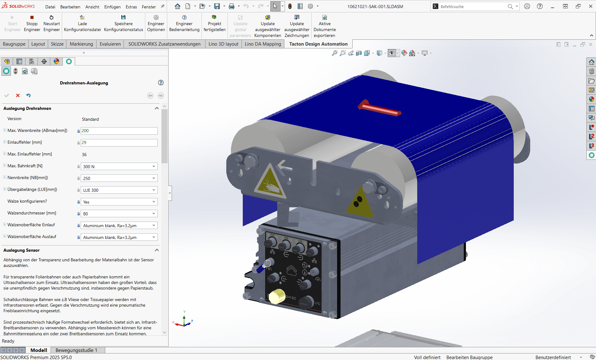
Transforms expert knowledge into intelligent rules to automatically generate complex 3D models, drawings, and bill of materials—saving up to 90% of engineering time.
Lino® Hub
Seamlessly connects sales, engineering, and manufacturing for end-to-end digital processes.
Seamlessly integrates CPQ, CAD, ERP, and PDM for error-free, automated data flows without media breaks.
Lino® Automate
Transforms routine CAD tasks into fully automated workflows using intelligent action lists and seamlessly integrates them with PDM, PLM, or ERP systems—for maximum time savings.
Lino® 2D fix
Drawing automation without manual adjustments for production-ready layouts.
Automatically optimizes drawing layouts, avoids dimension conflicts, and dynamically adjusts scales.
Lino® 3D layout
Uses drag-and-drop and snap technology for collision-free layouts. Ensures seamless data flow from sales to installation without any data loss.

Relevant Processes for Conveyor Systems and Hoists
Lino supports digital engineering processes for conveyor systems and hoists. Connecting system integration, configuration, and automation into a seamless value chain. This covers the entire process: from the first customer contact through to the finished machine system
Design Automation for Rapid Product Development
Optimize your design process with Design Automation and CAD automation. Product rules automatically generate 3D CAD models, 2D drawings, and bills of materials. This accelerates engineering processes, reduces errors, and significantly decreases routine engineering tasks.
Product Configuration for Individual Customer Solutions
Master product variety with a product configurator and CPQ system. Using rule-based variant configuration and guided selling, sales teams, partners, and customers create technically valid product variants, quotes, and configuration data – directly integrated into CAD and ERP systems.
System Integration for a Seamless Corporate IT Landscape
Connect your IT systems into a continuous data chain. Through system integration in mechanical engineering, CAD, ERP, CRM, and PDM/PLM systems are seamlessly linked. This creates a consistent digital thread along the entire product lifecycle.
Visualizing 3D Products in the Web Browser
With 3D product visualization on the web, you can present complex products interactively in the browser. Thanks to modern technologies such as WebGL 3D viewers, variants can be displayed in real time and directly linked to configurators or web shops.
Generating Technical Drawings Automatically
Create technical drawings automatically from 3D CAD models. Drawing automation generates standards-compliant manufacturing documentation, automatically adjusts layouts, and reduces manual rework after model changes.
3D Layout Planning for Modern, Impressive Plant Layouts
Plan entire plants with 3D layout planning and digital factory planning. With CAD-based 3D plant planning, you can create layouts, detect collisions early, and validate projects faster.
Together, we analyze your existing workflows and identify concrete potential for more efficient, digital processes – practical, structured, and with a clear focus on measurable value.
- Analysis of your engineering and sales processes
- Identification of optimization potential
- Clear roadmap for your digital transformation
See for Yourself

Frequently Asked Questions for Conveyor Systems and Hoists
The FAQs answer questions about the conveyor systems and hoists industry in the context of the Lino portfolio.
Find answers about standards-compliant configuration and automated engineering of conveyor systems, bridge cranes, and hoisting equipment. Learn how Tacton CPQ validates FEM classifications, calculates girder cross-sections, and dimensions hoisting mechanisms in accordance with standards – and how Lino 3D layout integrates conveyor systems collision-free into existing halls, reduces manual layout work by up to 80%, and delivers quotations with complete 3D visualization in days rather than weeks.
How does Lino Hub seamlessly connect the configuration and engineering process for conveyor technology with PDM and ERP?
Lino Hub serves as the central integration platform between Tacton CPQ, Tacton Design Automation, the CAD system, the PDM/PLM system, and the ERP. After order confirmation, Lino Hub automatically transfers the complete bill of materials – girder profiles, crab unit, hoisting mechanism, travelling gears, drives, standard parts, and purchased components – to the ERP and validates part number consistency. Technical drawings and 3D models are versioned and stored in the PDM/PLM system, linked to the machine bill of materials. The entire process from configuration to production order is end-to-end digitized – manual data handovers, transfer errors, and delivery delays caused by missing purchased parts are a thing of the past.
How does Lino reduce the quotation cycle for conveyor technology and cranes from weeks to days?
The combination of Tacton CPQ for standards-compliant configuration and technical sizing, Tacton Design Automation for fully automated 3D model generation, Lino 3D layout for layout planning in existing halls, and Lino 2D fix for drawing automation eliminates the typical three to five iteration loops between sales, project engineering, and design. Manufacturers report 60% faster quotation preparation. In a market where delivery times are a decisive competitive factor, this means not only faster order closures but also the ability to handle significantly more inquiries with the same headcount – as in the case of motion06, where 500 variants were handled in the first year through the configuration solution alone.
How does Lino automatically generate standards-compliant quotation drawings for hoisting equipment such as wire rope hoists and chain hoists?
Lino 2D fix automatically derives standards-compliant quotation drawings from the 3D model generated by Tacton Design Automation. For hoisting equipment, this includes not only geometric dimensions but also industry-specific specifications such as suspension details, hook load diagrams, connection points, and safety markings in accordance with EN 14492. The tool places views, sections, and dimensions in compliance with standards and dynamically adjusts scales. Sales can dispatch the complete technical quotation – including 3D model and standards-compliant drawing – within a few hours, without a single query to engineering.
How does Lino 3D layout enable collision-free layout planning of conveyor systems in existing halls?
Lino 3D layout allows the floor plan of an existing hall – including column grid, roof trusses, elevation data, utility routes, and existing machinery – to be imported as a reference model. Conveyor belt modules, curve elements, transfer stations, buffer zones, and cranes are placed within this context using drag-and-drop. The system automatically checks for collisions with hall columns, building elements, and existing installations, and calculates conveyor routes, incline angles, and transfer heights. The customer receives a walkable 3D visualization of the complete conveyor system as a release and investment basis – during the quotation phase, with up to 80% less manual layout work compared to conventional 2D planning.
How does Tacton Design Automation automate the engineering of bridge cranes with individual spans and lifting capacities?
After configuration is completed in Tacton CPQ, Lino Hub transfers the parameters to Tacton Design Automation. Design Automation then fully automatically generates the complete parametric 3D CAD model of the bridge crane: main girder in the calculated profile size and span, end carriages, crab unit with hoisting mechanism, travelling gears, control equipment mounting, and all connection elements. Customer-specific requirements such as non-standard track gauges, specific rail profiles, or explosion-proof designs are stored as rule sets. What previously required three to five iterations between sales, project engineering, and design is completed in days – with up to 90% time savings in engineering.
How does Tacton CPQ ensure that bridge cranes are configured in compliance with FEM classification and EN 15011?
Tacton CPQ maps the normative requirements for bridge cranes – FEM classifications according to duty class and load cycle count, requirements of EN 15011, and the Machinery Directive – directly as constraints within the configuration rule set. Sales staff enter span, lifting capacity, lift height, and operating conditions. The system automatically calculates the required FEM class, dimensions the girder cross-section, and assigns the hoisting mechanism and travelling gear with the correct safety factors. Non-compliant combinations are excluded by design – the result is a 100% standards-compliant configuration without a standards expert having to check manually.
Managing variants and accelerating quotations for conveyor systems and hoists – Lino enables this through intelligent configuration and integrated engineering automation.